We use cookies to ensure you get the best experience on our website. For more information on how we use cookies, please see our cookie policy.
By clicking "Accept", you agree to our use of cookies.
Learn more.
Technical documents and specifications for this product.
FMS_300 Datasheet
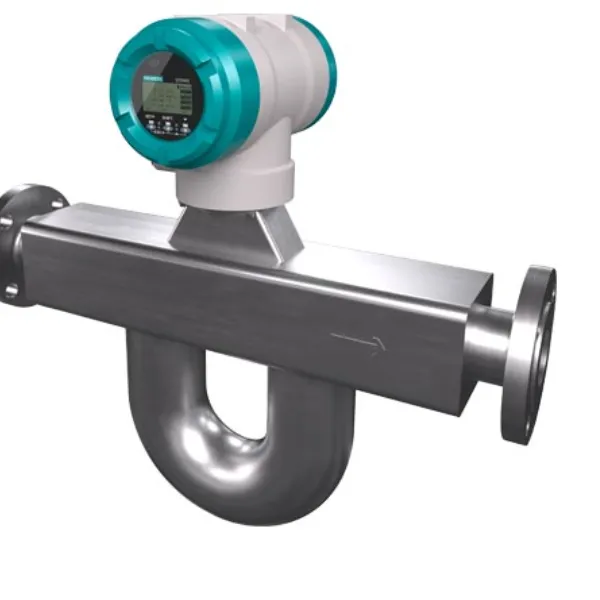
FCT020 is the standard transmitter, suitable for general purpose applications. It delivers accurate and precise measurements of mass flow rate, density, temperature and volume flow rate.
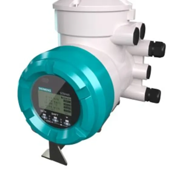
The FCT020 transmitter is available in compact or remote design and can be combined with all SITRANS FC sensors. The selection is made within the complete SITRANS FC ordering code.
Spare transmitters are selected using the SITRANS FC ordering code, but with no sensor selected.
Order code: S12
Tube health check monitors key diagnostics, including tube stiffness, driver and pickups. Self-verification alerts to potential performance issues due to unplanned process events, for example gas or vapor breakout, or solid deposits building up in the tubes. The user defines verification frequency and alarm behavior. Verification results indicate whether preventive maintenance action is required.
Up to 4 combined inputs and outputs
The table below provides a matrix of all available combinations for FCT020 transmitters.
Each combination is defined by a blend of two order code options:
Abbreviations used in the table:
*(Note: The table from the original text is not included here for brevity. It's recommended to refer to the datasheet for this detailed configuration information.)*
| Specification | Value |
|---|---|
| Housing material options | Coating / Design / Order code position 14 |
| Cast aluminum alloy Al-Si10Mg(Fe) | Standard coating / Remote transmitter / C or D |
| Cast aluminum alloy Al-Si10Mg(Fe) | Corrosion resistant coating / Remote transmitter / E or F |
| ASTM CF8M stainless steel | None / Remote transmitter / G or H |
| Display | Material of the lid window: Glass |
| Mounting bracket | Material: AISI 316L stainless steel / Mat. no. 1.4404 (Only the remote transmitters are supplied with a mounting bracket.) |
| Nameplates | Transmitter with cast aluminum housing: Not applicable / Foil Transmitter with ASTM CF8M stainless steel housing: Not applicable / AISI 316L ss (Nameplate material depends on the materials selected for SITRANS FC sensors.) |
| Process temperature range |
| Specification | Value |
|---|---|
| Power supply | Alternating current voltage (rms): nominal 24 V AC (-15% ... +10%), or 100 ... 240 V AC (-20% ... +10%) / Frequency: 47 ... 63 Hz / Direct current voltage: nominal 24 V DC (-15% ... +20%) or 100 ... 120 V DC (-10% ... +8.3%) / Power consumption: P ≤ 10 W (including sensor) |
| Power supply failure | In the event of a power failure, the flowmeter data are backed up on a non-volatile internal memory. In case of devices with display, the characteristic sensor values, such as nominal diameter, serial number, calibration constants, zero point and the error history are also stored on a microSD card. |
| Galvanic isolation | All circuits for inputs, outputs and power supply are galvanically isolated from each other. |
| Analog inputs and outputs | Analog input: FCT020 transmitters cannot be specified with analog current input. / Analog output: Up to 2 analog outputs can be selected at time of ordering. The analog outputs can be configured to represent the following measured values: Flow rate (mass, volume, net partial component flow of a mixture) / Density / Temperature / Pressure / Concentration / HART communication, when selected, is supplied on channel 1 (I/O 1). The current output may be operated in compliance with the NAMUR NE43 standard. |
| Analog outputs | Active output: Nominal output current range 4 ... 20 mA / Maximum output current range 2.4 ... 21.6 mA / Load resistance ≤ 750 Ω / Load resistance for secure HART communication 230 ... 600 Ω / Passive output: Nominal output current range 4 ... 20 mA / Maximum output current range 2.4 ... 21.6 mA / External power supply 10.5 ... 32 VDC / Load resistance for secure HART communication 230 ... 600 Ω / Load resistance at current output ≤ 911 Ω |
| Specification | Value |
|---|---|
| Digital inputs (status) | Do not connect a signal source with electric voltage. / The status input is provided for use of voltage-free contacts with the following specification: Resistance when closed < 200 Ω / Resistance when open > 100 kΩ |
| Digital outputs | Digital outputs: Active pulse output available on Pulse/Status output, connection of an electronic counter / Load resistance > 1 kΩ / Internal power supply 24 V DC ±20% / Maximum pulse rate 10 000 pulses/s / Frequency range 0 ... 12.5 kHz / Active pulse output available on Pulse/Status output, connection of an electromechanical counter / Maximum current 150 mA / Average current ≤ 30 mA / Internal power supply 24 V DC ±20% / Maximum pulse rate 2 pulses/s / Pulse width 20, 33, 50, or 100 ms / Active pulse output available on Pulse/Status output, with internal pull-up resistor / Internal power supply 24 V DC ±20% / Internal pull-up resistor 2.2 kΩ / Maximum pulse rate 10 000 pulses/s / Frequency range 0 ... 12.5 kHz / Passive pulse output available on Pulse/Status output / Maximum load current ≤ 200 mA / External power supply ≤ 30 V DC / Maximum pulse rate 10 000 pulses/s / Frequency range 0 to 12.5 kHz / Active status output available on Pulse/Status output / Load resistance > 1 kΩ / Internal power supply 24 V DC ±20% / Active status output available on Pulse/Status output, with internal pull-up resistor / Internal pull-up resistor 2.2 kΩ / Internal power supply 24 V DC ±20% / Passive status output available on Pulse/Status output, or Status output / Output current ≤ 200 mA / External power supply ≤ 30 V DC / Passive pulse or status output available on Pulse/Status output (NAMUR) / Output signals according to EN 60947-5-6 (previously NAMUR, worksheet NA001) |
| Specification | Value |
|---|---|
| Each transmitter is configured with one default digital communication interface, selectable in the SITRANS FC order code. | |
| HART | When selected, HART communication is supplied on the output terminal pair I/O 1. / Up to 3 further input/output options can be configured for output terminal pairs I/O 2, I/O 3, and I/O 4. / HART is available with either non-intrinsically safe or intrinsically safe outputs. |
| PROFIBUS PA | When selected, PROFIBUS PA communication is supplied on the output terminal pair I/O 1. / PROFIBUS PA interface is available with and without intrinsic safety. / PROFIBUS PA digital communication signal is in accordance with IEC 61158/61784. / Maximum voltage and correct polarity must be observed for wiring. / Power supply: 9 ... 32 V DC / Current draw: 15 mA (maximum) / Compliance with PA profile revision 3.02 supporting: Condensed Status (NE107) / Device identification number (IDENT_NUMBER) adaption / Summary of available function blocks – PROFIBUS PA (Note: Table content omitted for brevity - see datasheet) |
| MODBUS | (in preparation for later release) / The MODBUS interface is available with up to two additional input/output options. / When selected, MODBUS communication is supplied on the terminal pairs I/O 3 and I/O 4. / The digital MODBUS communication signal is in accordance with EIA-485 standard (RS 485). |
| PROFINET over Ethernet-APL | (in preparation for later release) |
| Specification | Value |
|---|---|
| Type | 4-line dot-matrix display |
| Resolution | 128 × 64 (W × H) dots |
| Size | 64.6 × 31.2 mm (2.54" × 1.23") |
| Control | via IR switches / Numerical values entered via the display are limited to six digits for process variables and eight digits for totalizer. |
| Specification | Value |
|---|---|
| Type | Industrial Grade microSD card, compliant with SD specification version 2.0 |
| Physical dimension | 15 × 11 × 1.0 mm (± 0.1 mm) (0.6 × 0.4 × 0.04 inch (± 0.004 inch)) |
| Capacity | 1 GB |
| Sequential throughput (read) | 24.01 MB/s |
| Sequential throughput (write) | 17.96 MB/s / It is recommended to use the microSD card included with the SITRANS FCT transmitter. Functionality of the device cannot be guaranteed if other cards are used. |
For remote type devices, an interconnecting cable must be used to connect the sensor to the transmitter. The device specifications, stated in this document, are valid only if one of the original SITRANS FC interconnecting cables is used.
Standard cable length options are specified up to 30 m are specified in the order code to maintain the stated specifications. Cables longer than 30 m (98 ft) are available but must be ordered as separate items. For further details, please contact your regional Siemens Measurement Intelligence team.
(Note: The dimensional drawings are not included here. Refer to the datasheet.)
| Design type | Transmitter enclosure material | Weight in kg (lb) |
|---|---|---|
| Remote | Cast aluminum | 4.2 (9.3) |
| Remote | CF-8M stainless steel | 12.5 (27.6) |