We use cookies to ensure you get the best experience on our website. For more information on how we use cookies, please see our cookie policy.
By clicking "Accept", you agree to our use of cookies.
Learn more.
Technical documents and specifications for this product.
e_power_ip_datasheet
e_power_ip_manual
e_power_ip_quick_start_instructions
e_power_ip_product_sheet
e_power_ip_wiring
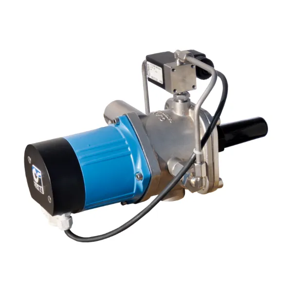
The CLA-VAL e-Power IP: Power from Flowing Water is an electrical generator system that autonomously harnesses available hydraulic energy directly from the water distribution network. It combines an electrical generator, a solenoid bypass shut-off, and a hydraulic differential pressure controller. The system is installed into the bypass of a CLA-VAL valve. The electrical box contains a 12V rechargeable lead-acid battery and an electronic charge management system, supplying continuous 14 Watt power at a differential pressure of 6 mhd and flow of 50 l/min. The e-Power IP generates 16 Watt to recharge the battery using the pressure drop across the valve. The efficiency between the power supplied by the battery and the generated power by the turbine is 88%. This system provides 12V and 24V output to power various devices located near or on the valve, such as motorized pilots, sensors, telemetry, PLCs, or HMI interfaces. The e-Power IP's innovative and patented design ensures compact management of differential pressure and energy production.
| Option | Description |
|---|---|
| LFS Option | Control Low flows or night flows. |
| KO Option | Extend valve life with Anti-Cavitation trim. |
| KG1 Option | Use stem cleaning for harsh water. |
| Maintenance | Check on periodic maintenance. |
| Environment | Adapt to high temperatures or frost risk. |
| Security | Add hydraulic safety back-up to your valve. |
| Protection | Remove excessive system overpressures. |
| Corrosion | Protect your valve with upgraded materials. |
| Mounting Versions | Factory mounted (FM), Retrofit kit mounted (RM), Wall mounted (WM). |
| Electrical Cable Length | 3 meters (L03) or 10 meters (L10) between turbine and junction box. |
| Battery Capacity | 12V/3.5 Ah (A35) or 12V/7.0 Ah (A70). |
| Valve Model Compatibility | NGE DN 100-600 (various tubing/fitting sizes) and GE/AE DN 65-400 (various tubing/fitting sizes). |
| Downstream Pressure Control | With (DPC) or without (XXX) AQUA 80-451 pressure reducer. |
| Tapered Thread | ISO 7-1 (turbine tapping Rp 3/4"). |
| Specification | Value |
|---|---|
| Power Output (Continuous) | 14 W |
| Voltage Output | 12 VDC and 24 VDC |
| Generated Power (to battery) | 16 W |
| Optimal Differential Pressure (across turbine) | 6 mhd |
| Optimal Flow | 50 l/min |
| Efficiency (battery supplied vs. generated) | 88% |
| Battery Type | Gelled lead acid waterproof VRLA, maintenance-free |
| Battery Alarm Output | Dry contact switch (closes at 11.5 V) |
| Battery Lifetime (20°C) | 5 to 7 years (2000 cycles for 80% capacity) |
| Discharge Rate (storage) | Approx. 2% per month for 24 months (20°C) |
| Output 12 VDC Continuous Current (60 min/h) | 1.16 A (14 W) |
| Output 12 VDC Peak Current (1 min/h) | 5 A (60 W) |
| Output 24 VDC Continuous Current (60 min/h) | 0.58 A (14 W) |
| Output 24 VDC Peak Current (1 min/h) | 2.5 A (60 W) |
| Electrical Connection | Moulded 3 meters cable |
| Temperature Range (PCB only) | -10°C to +80°C |
| Operating Pressure | PFA 10 bar |
| Protection | IP 68 (excluding solenoid), Reverse polarity & short circuit, 80°C stop high temperature |
| Strainer (for solenoid) | Screen 0.2 mm |